
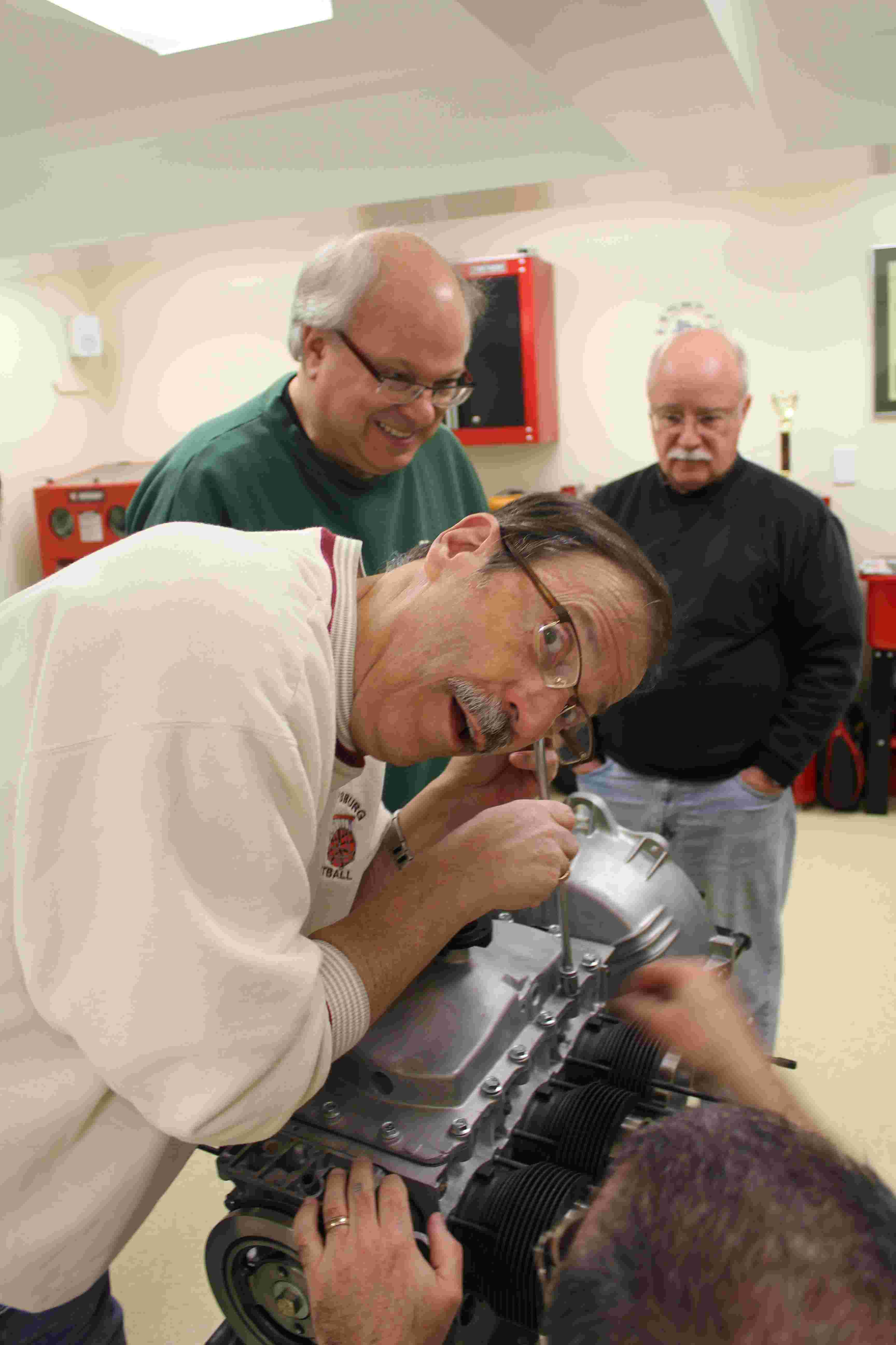
NJACE Tech Session - Engine Rebuild - Day 2 of 2.
Brian O'Neill checking oil pump gear clearance with a feeler gage.
Clearance is determined by the thickness of the gasket for the oil pump cover.
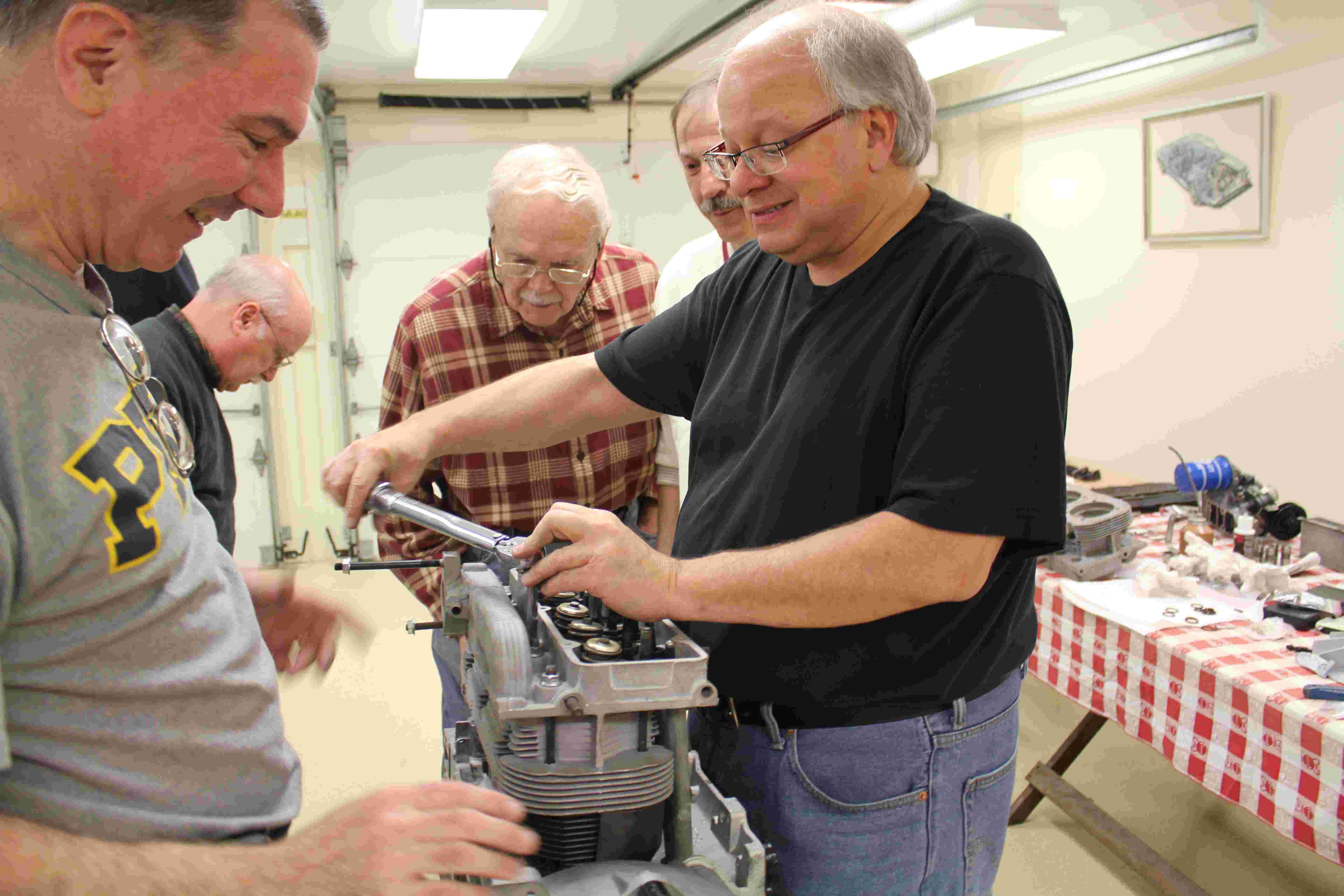
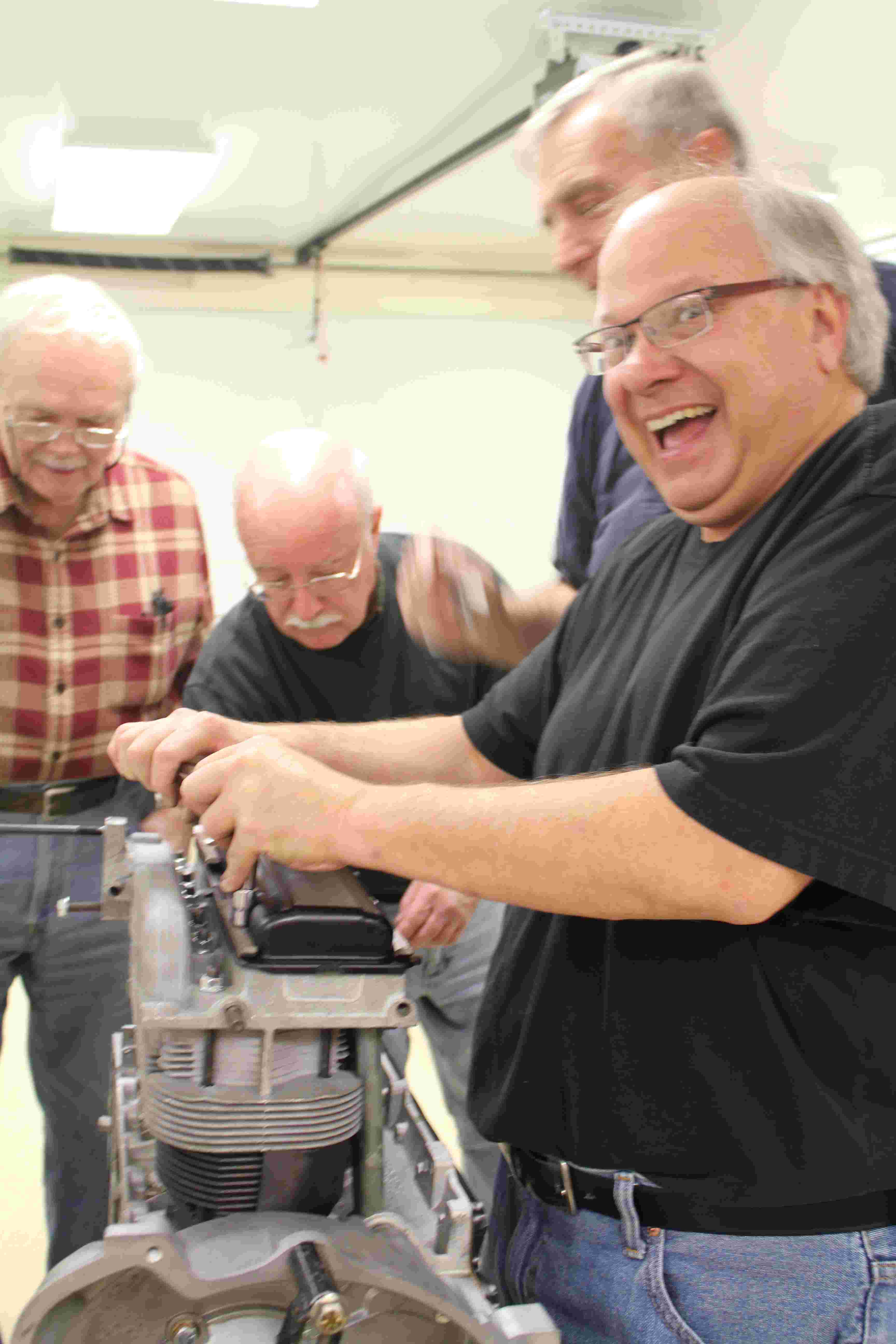
Driving home the oil pump cover bolts
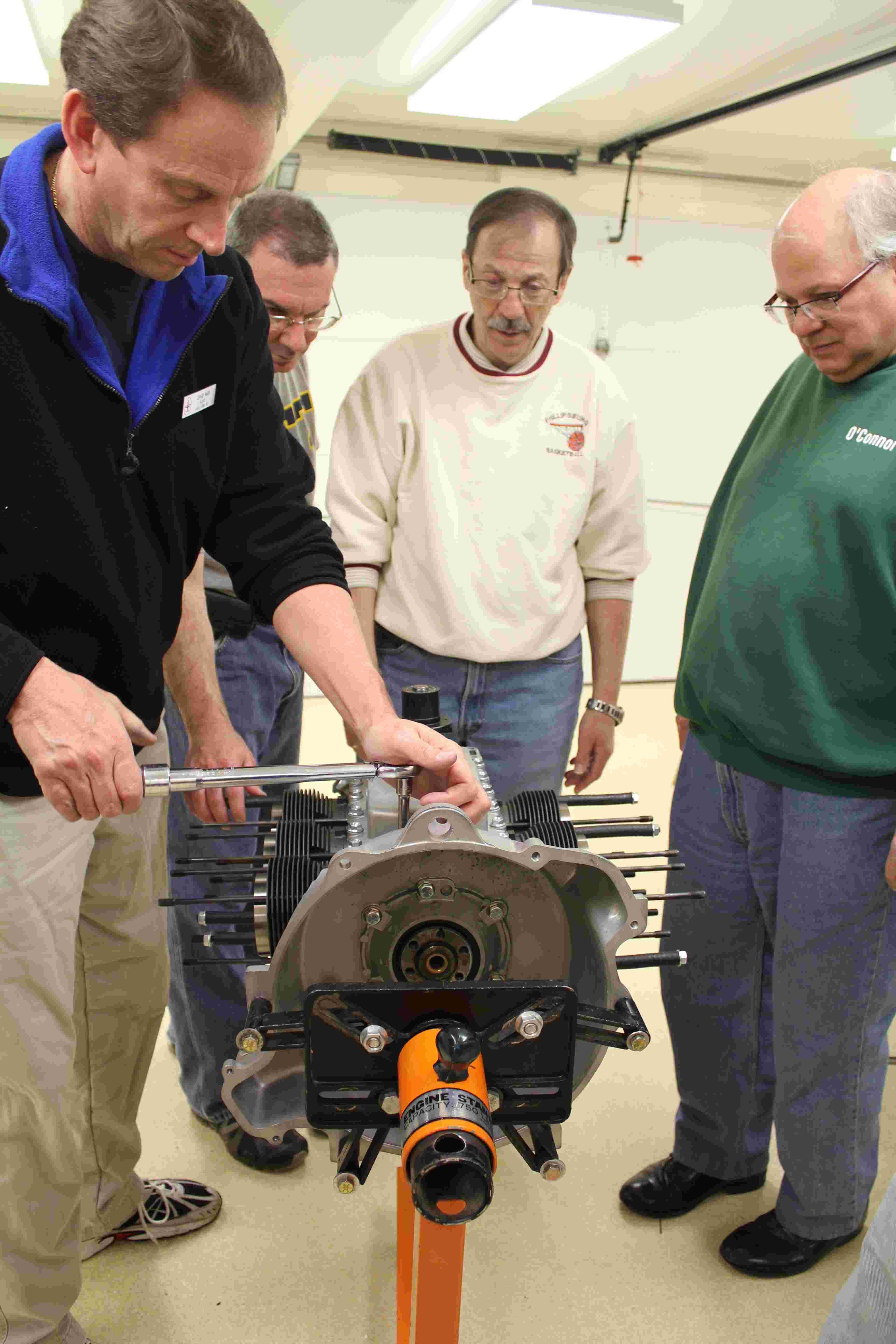
And finishing the job with a torque wrench.
When in doubt, lookup the torque specs in the Corvair shop manual.
Checking ring gap in the cylinders before installing the rings on the pistons.
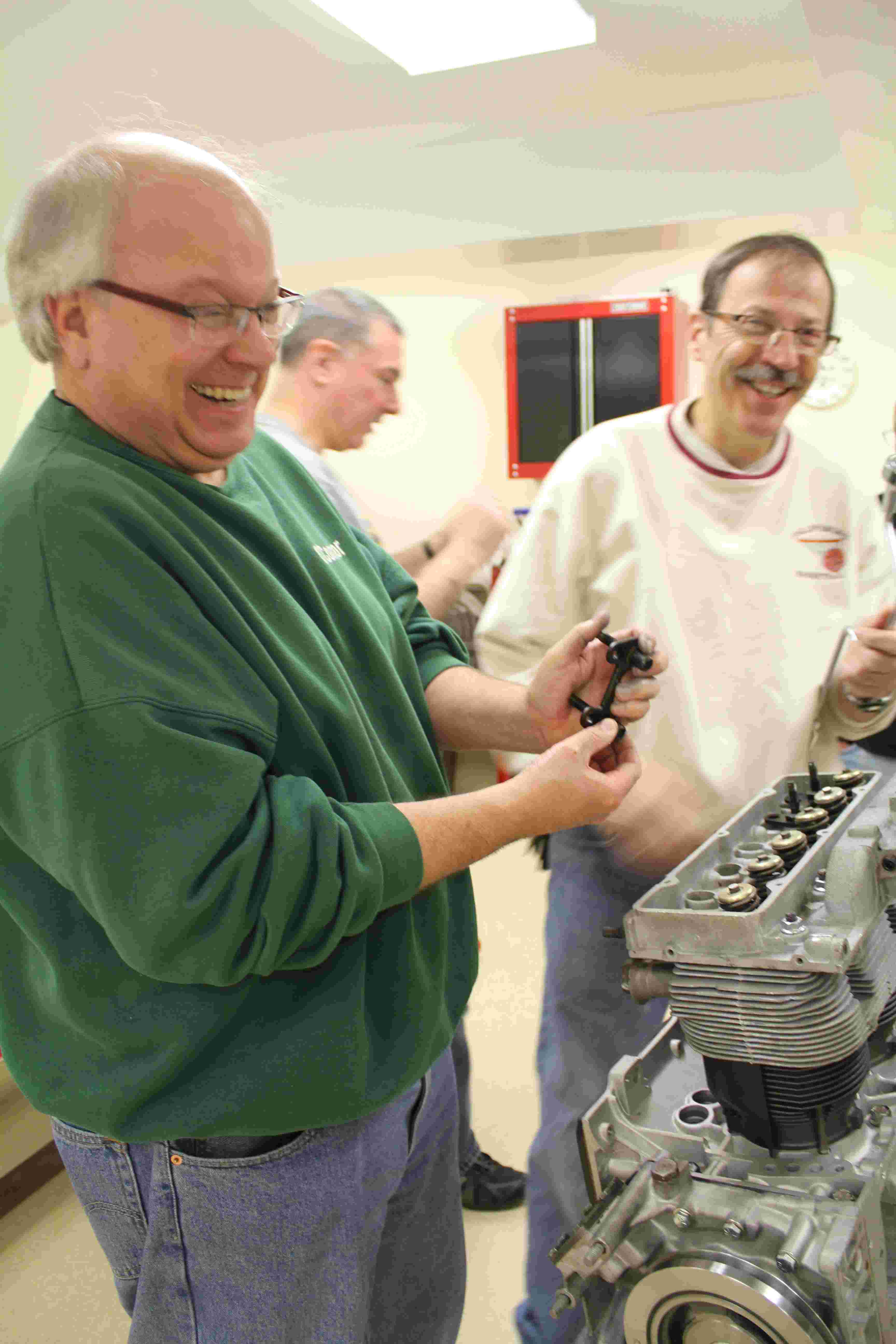
Brian installs the rings onto the pistons by hand.
Ken Schifftner prefers to install the rings with a special tool.
Al Lacki attempts to align the ring gaps so they are on opposite sides of the piston.
Brian inspects Lacki's work to ensure the ring gaps are properly aligned.
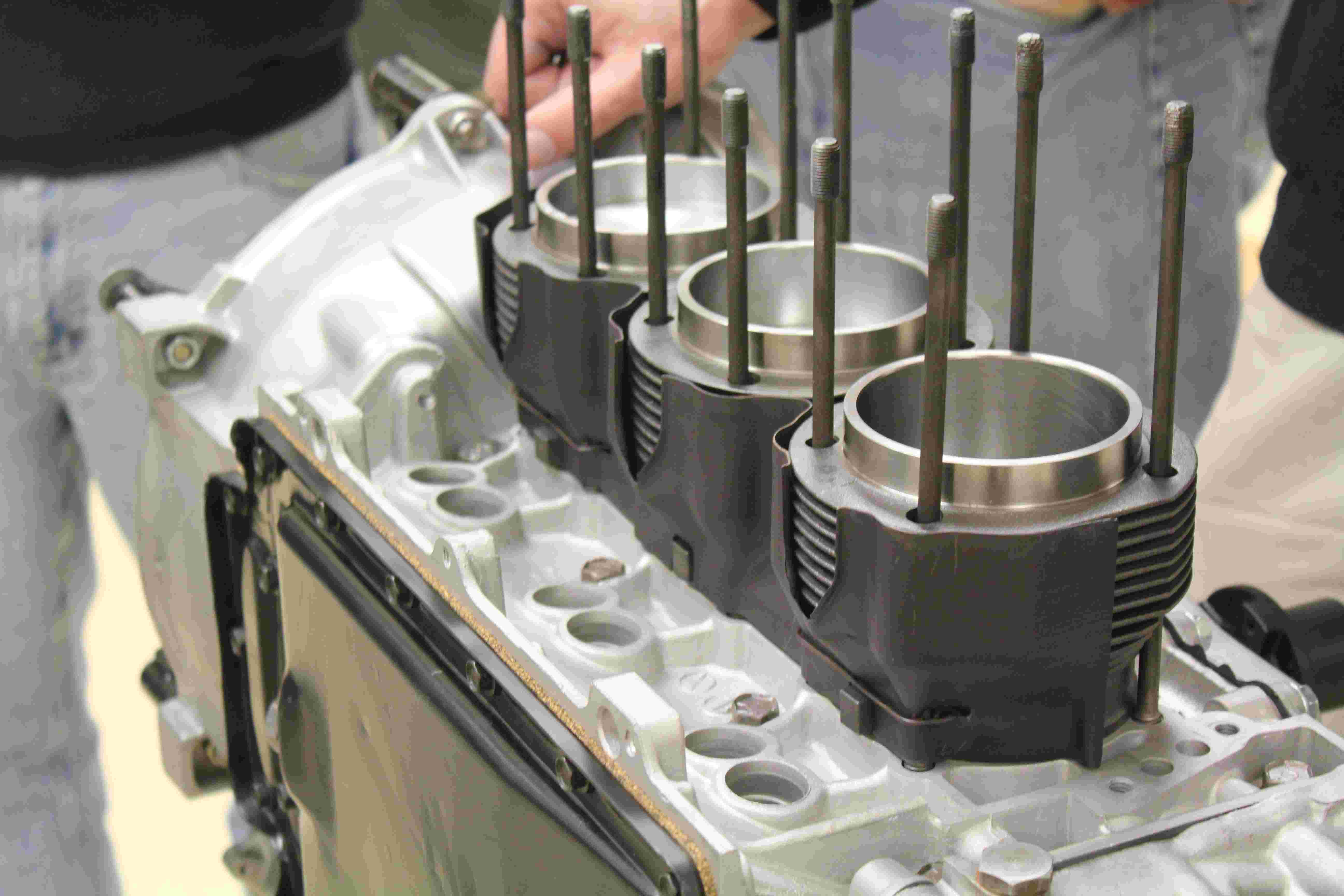
Installing one of the cylinder jugs on the crankcase.
Oops! We need to remove the top cover to install the rod caps!
Access to the rod cap nuts is through the top cover. Tight!
Lubing the journals before installing the rod caps.
All six cylinders finally installed.

Reinstalling the top cover, after installing the rod caps.
Installing the top cover. Be sure to include the tin baffles and gaskets inside!
Torquing the top cover bolts.
Lasagna-shaped air-baffles are installed with snap clips.
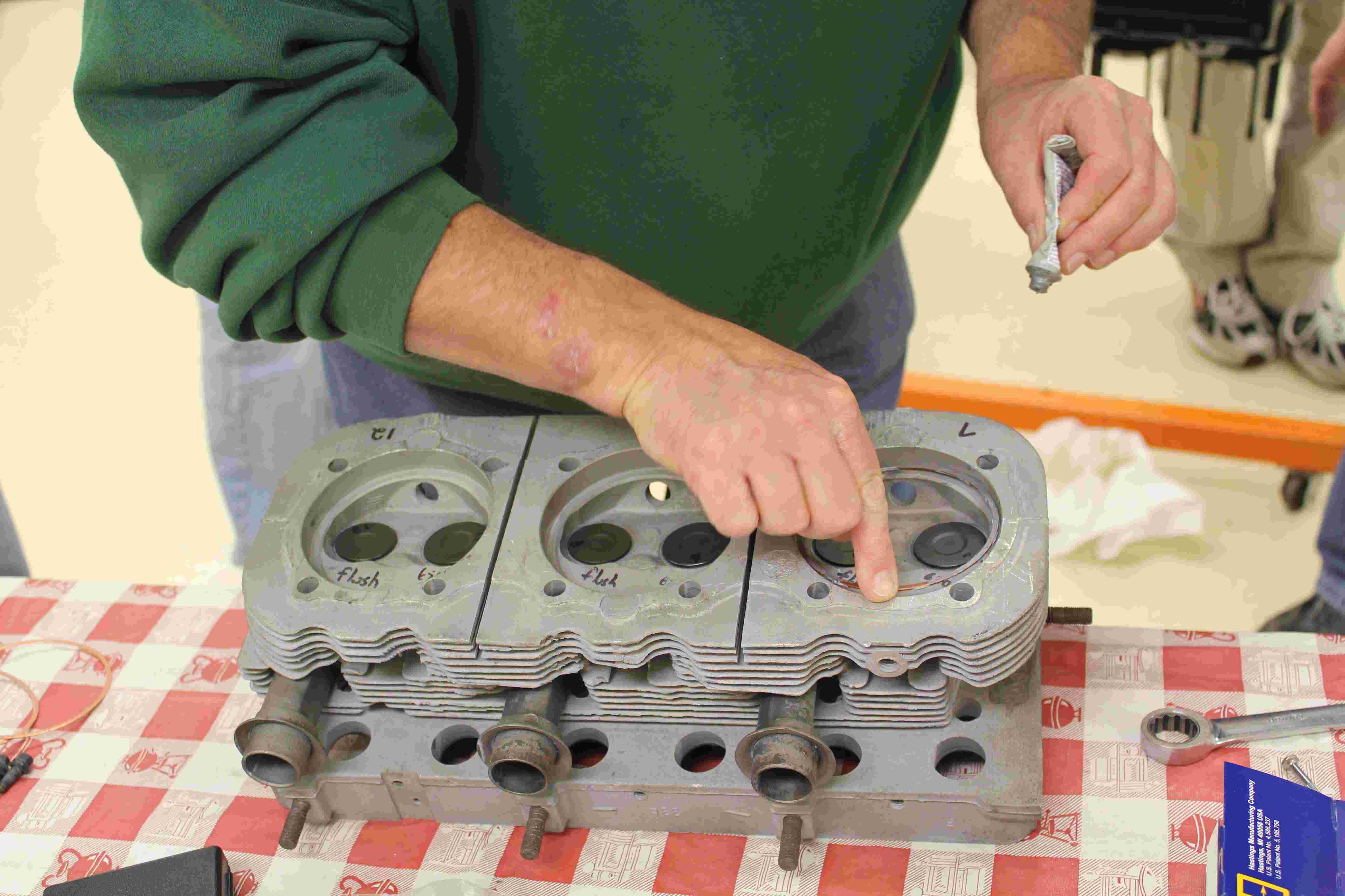
Smearing anti-seize on head gaskets and head gasket surfaces.
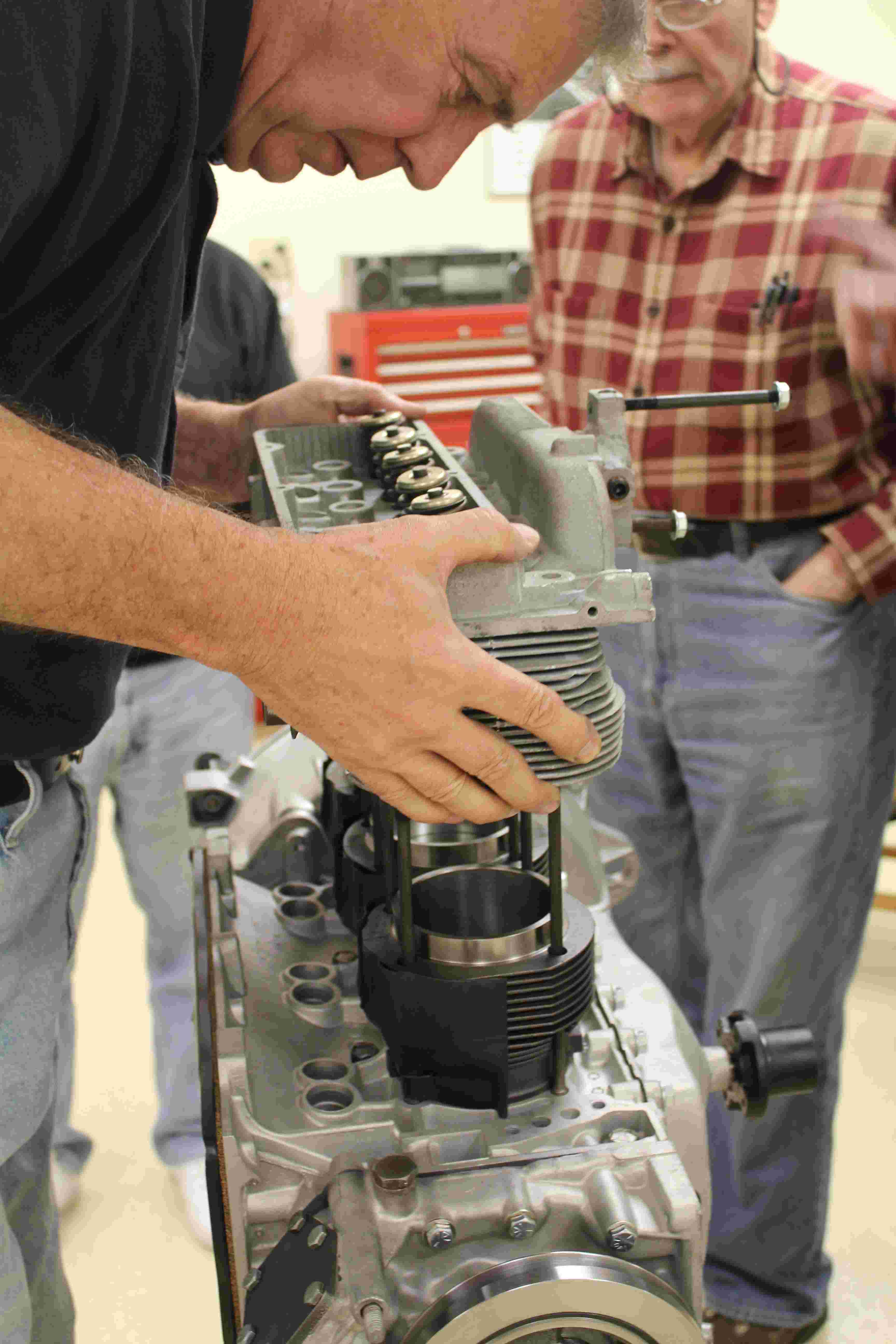
Fitting one of the two cylinder heads over the head studs.
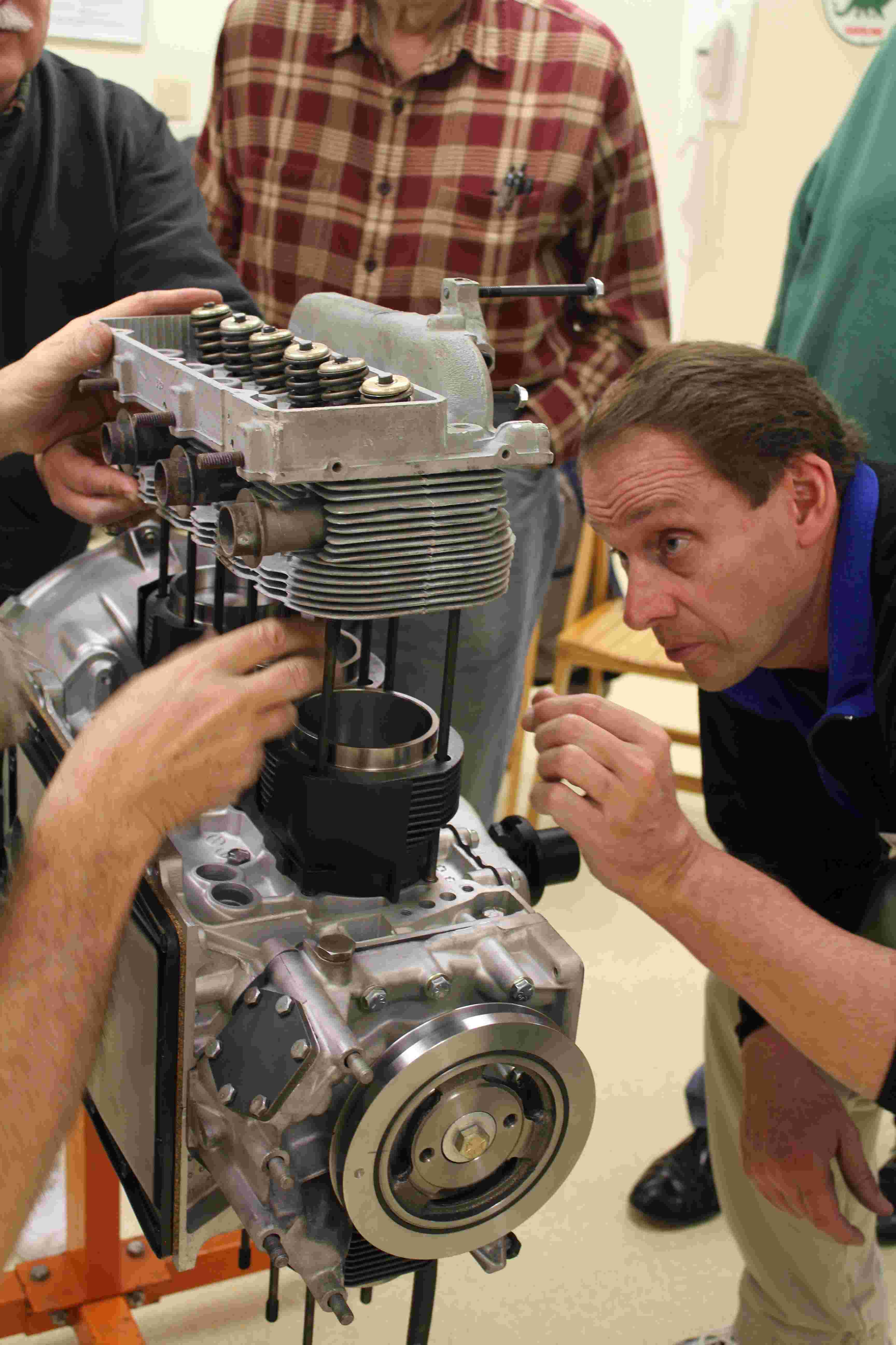
Sometimes, the head studs need persuasion to align with the holes in the heads.
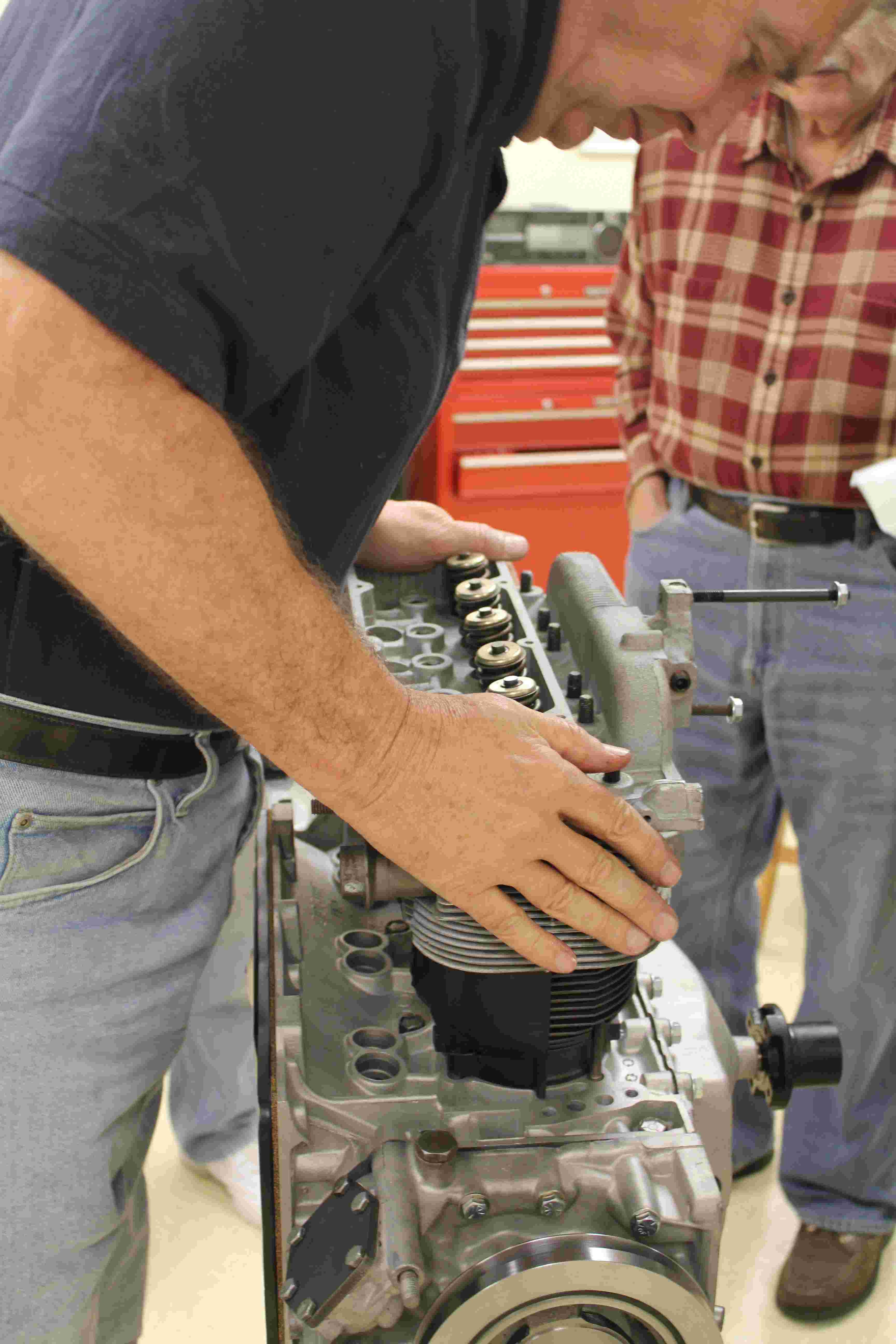
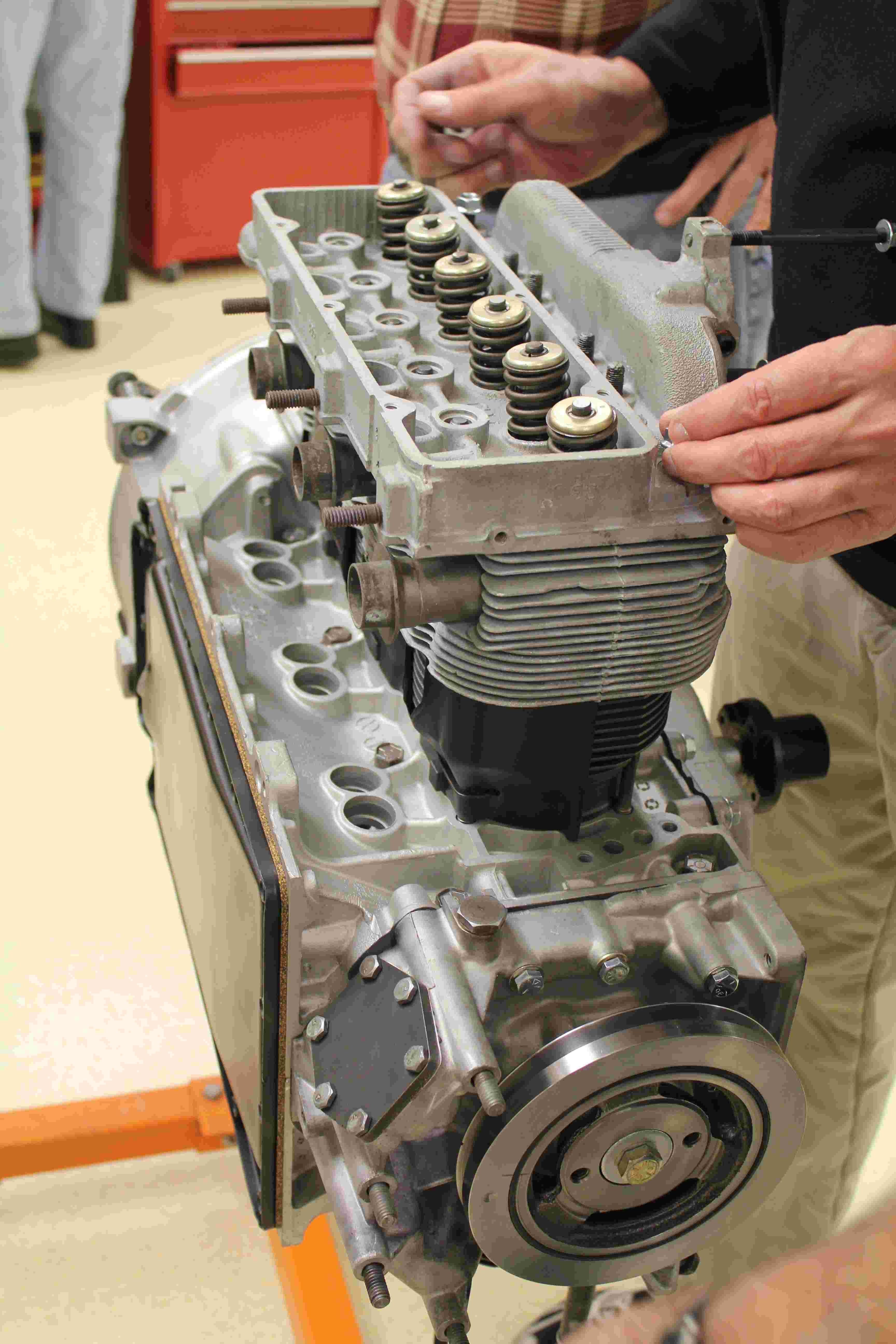
Pushing the head home.
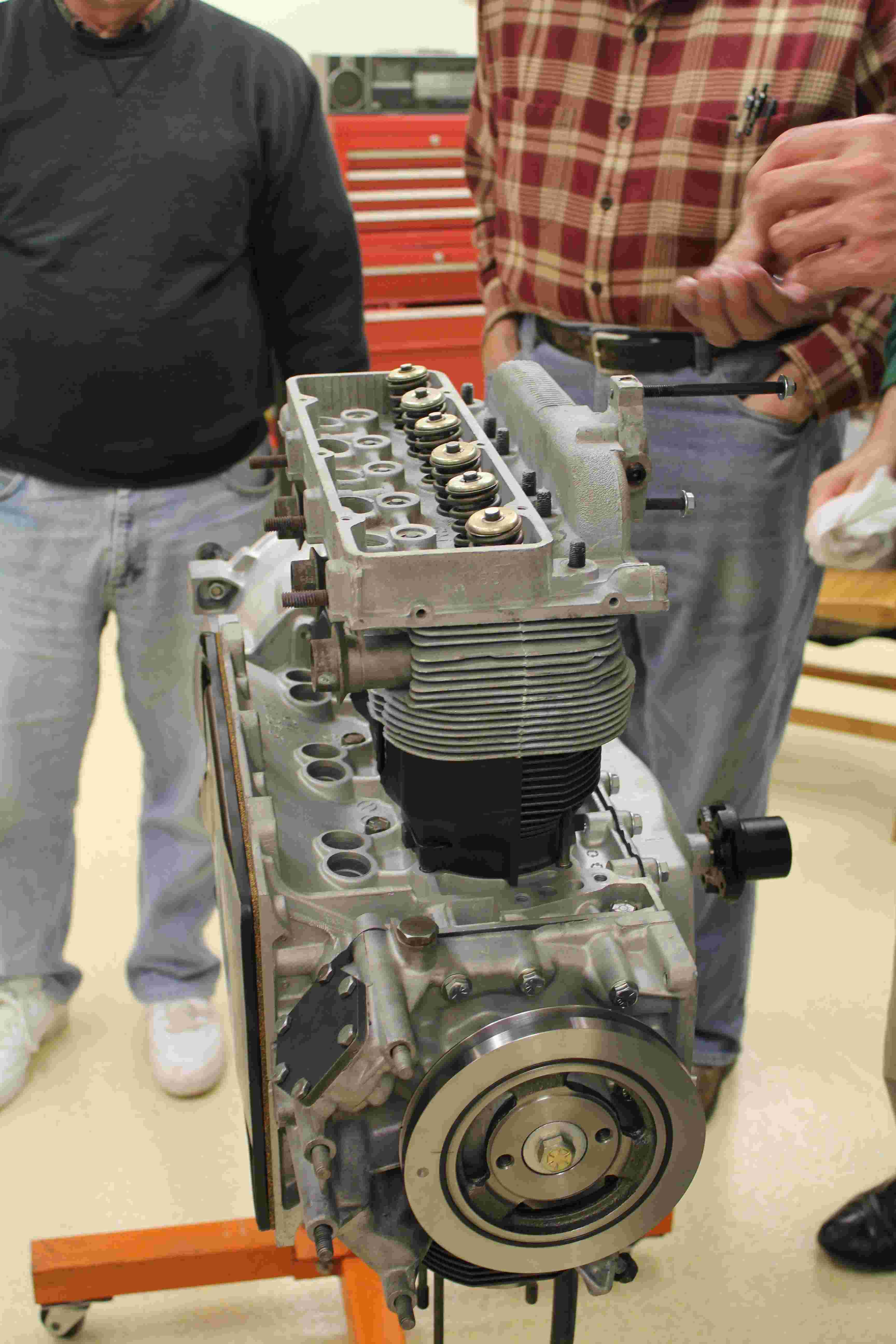
Getting ready to install head nuts.
First head nut gets screwed on. A combination of nuts and rocker arm studs keep the heads in place.
Al Lacki assembles the rocker arm studs onto push rod guide plates. A Viton o-ring goes on the back end.
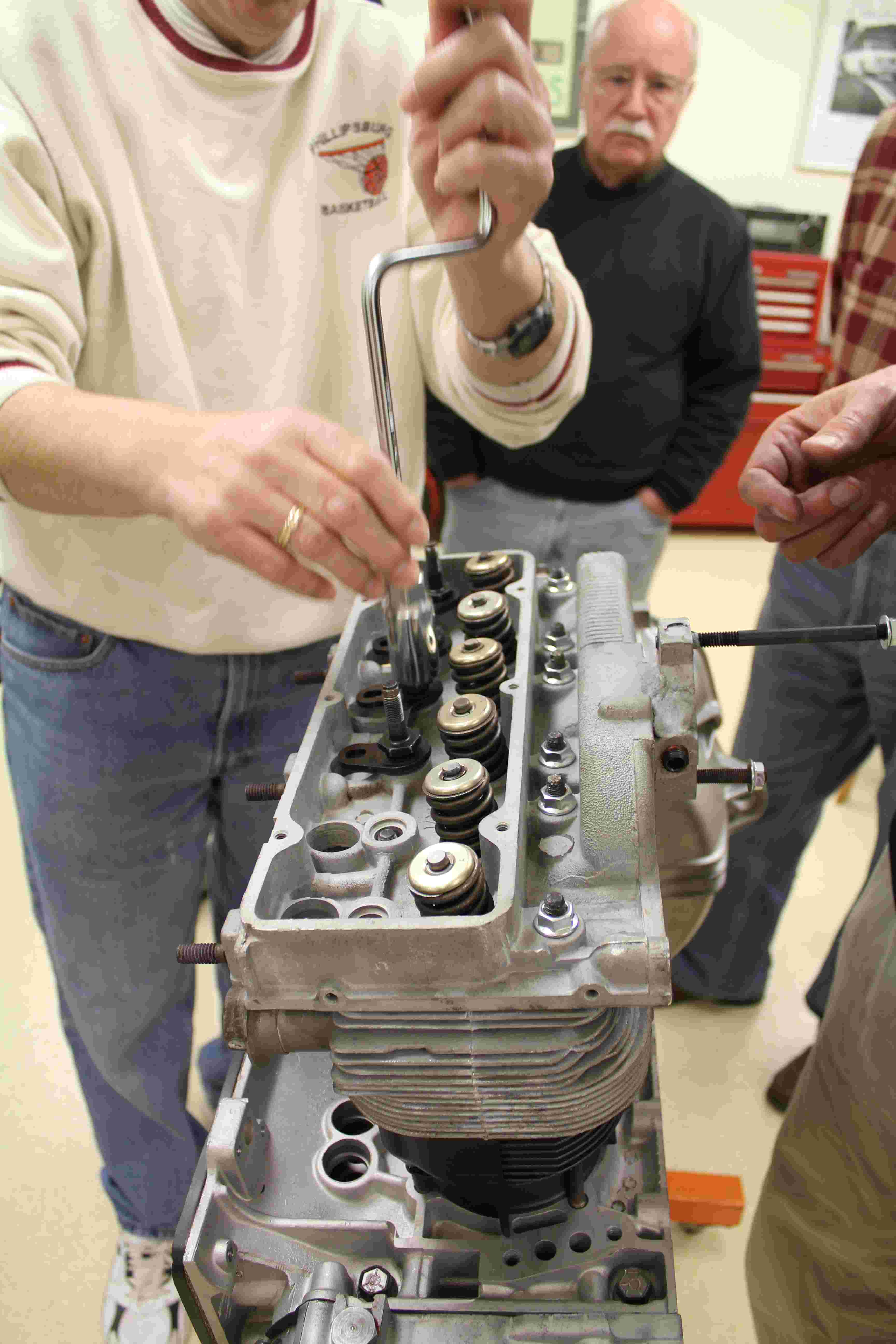
Joe uses a nut driver to snug down the rocker arm studs and head nuts.
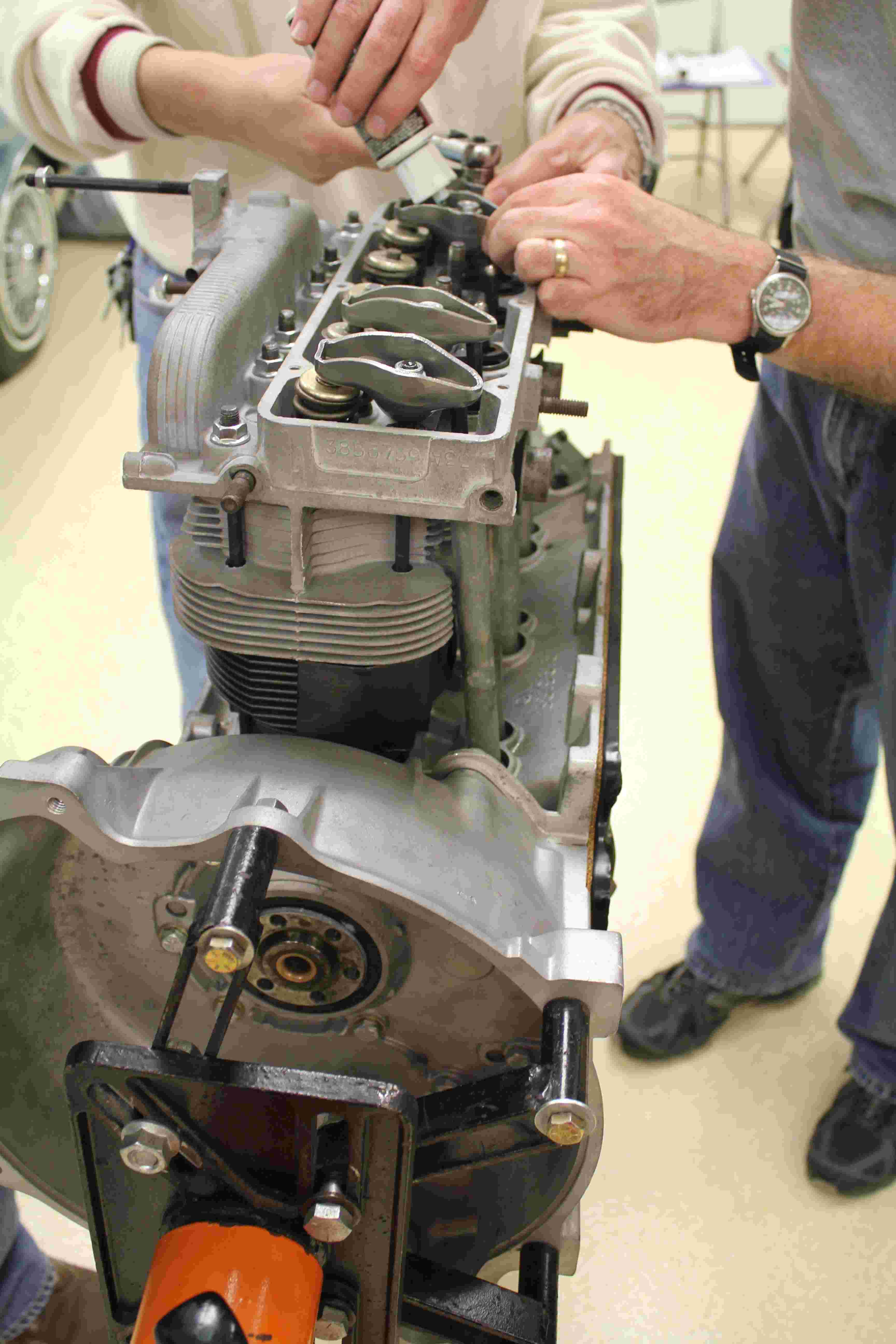
Lubing the rocker arm balls.
Torquing the rocker arm studs.
Torquing the head nuts. Rocker arm studs & head nuts must be torqued in steps & proper sequence.
Easy job! Installing a valve cover!
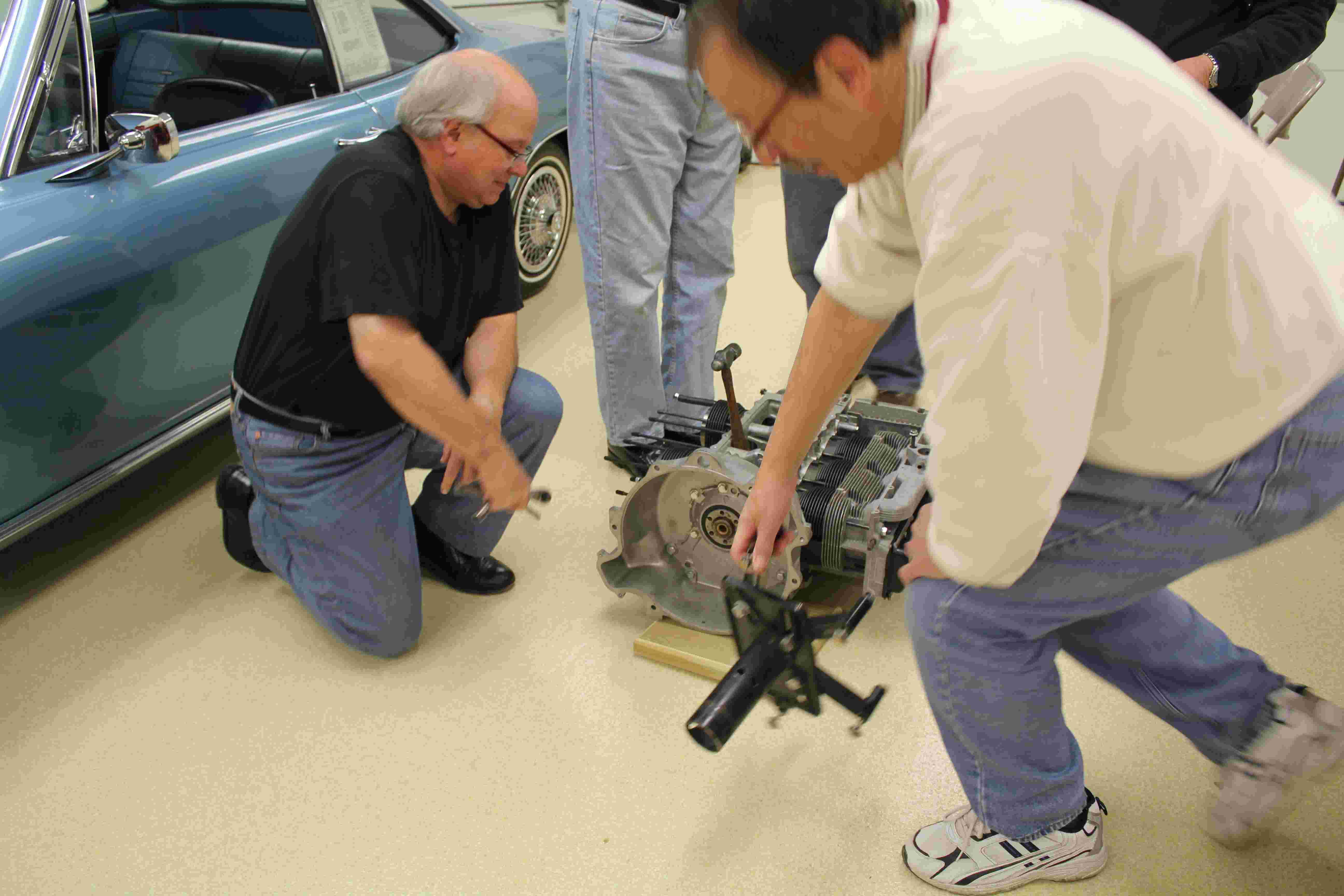
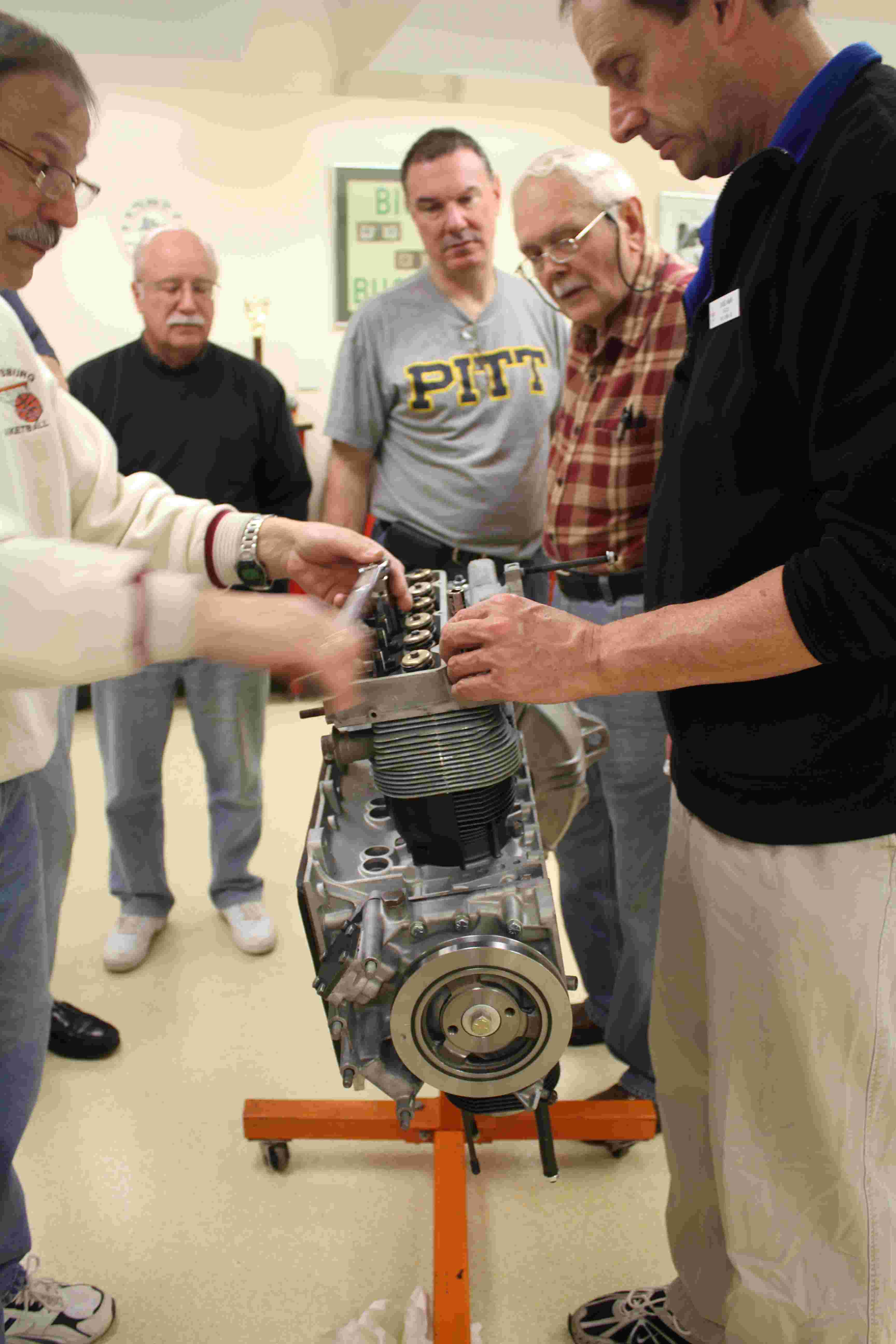
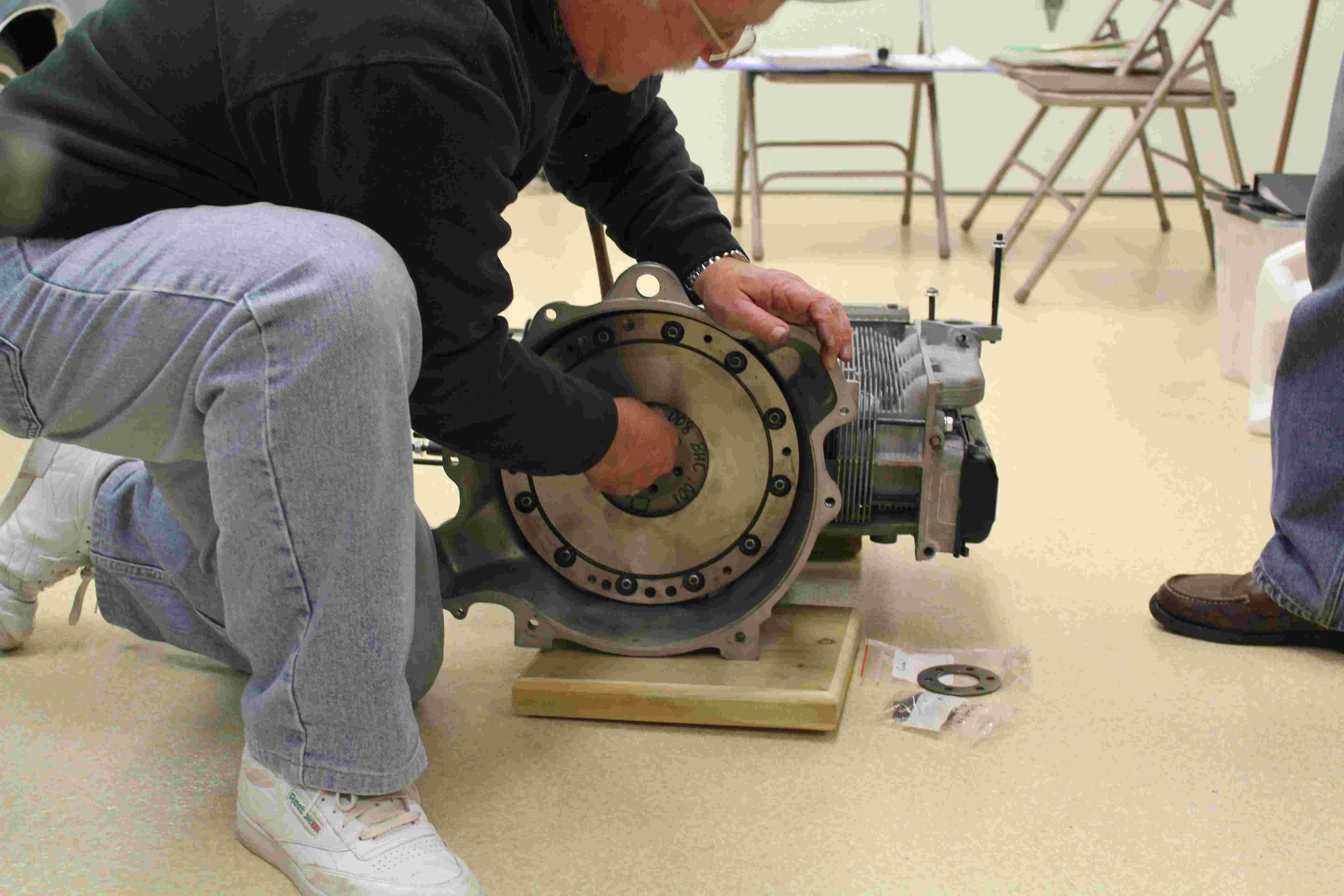
Several guys moved the engine to the floor.
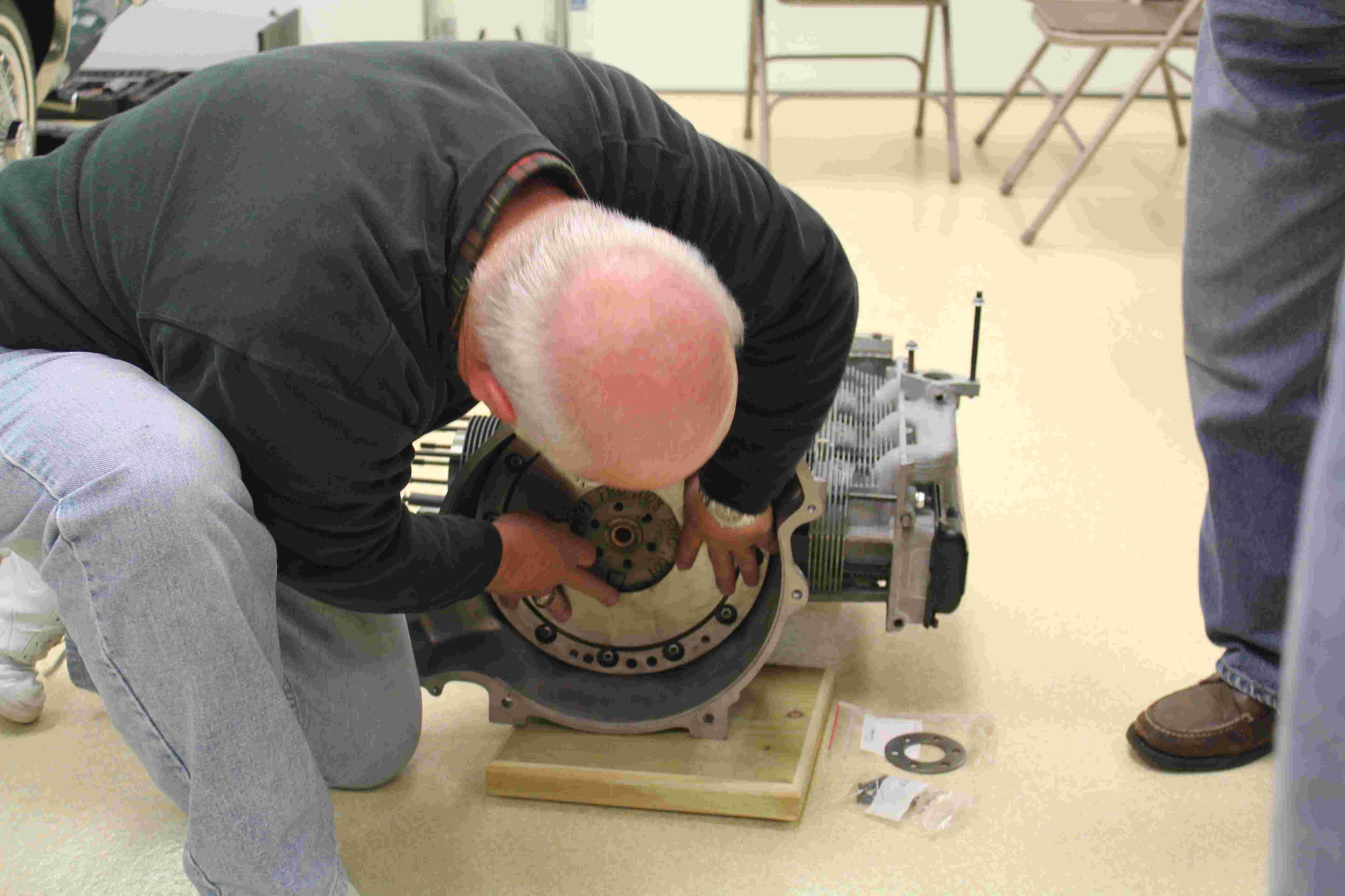
Ken Schifftner aligns the flywheel bolt holes to the end of the crank.
Ken Schifftner installing the flywheel bolts.
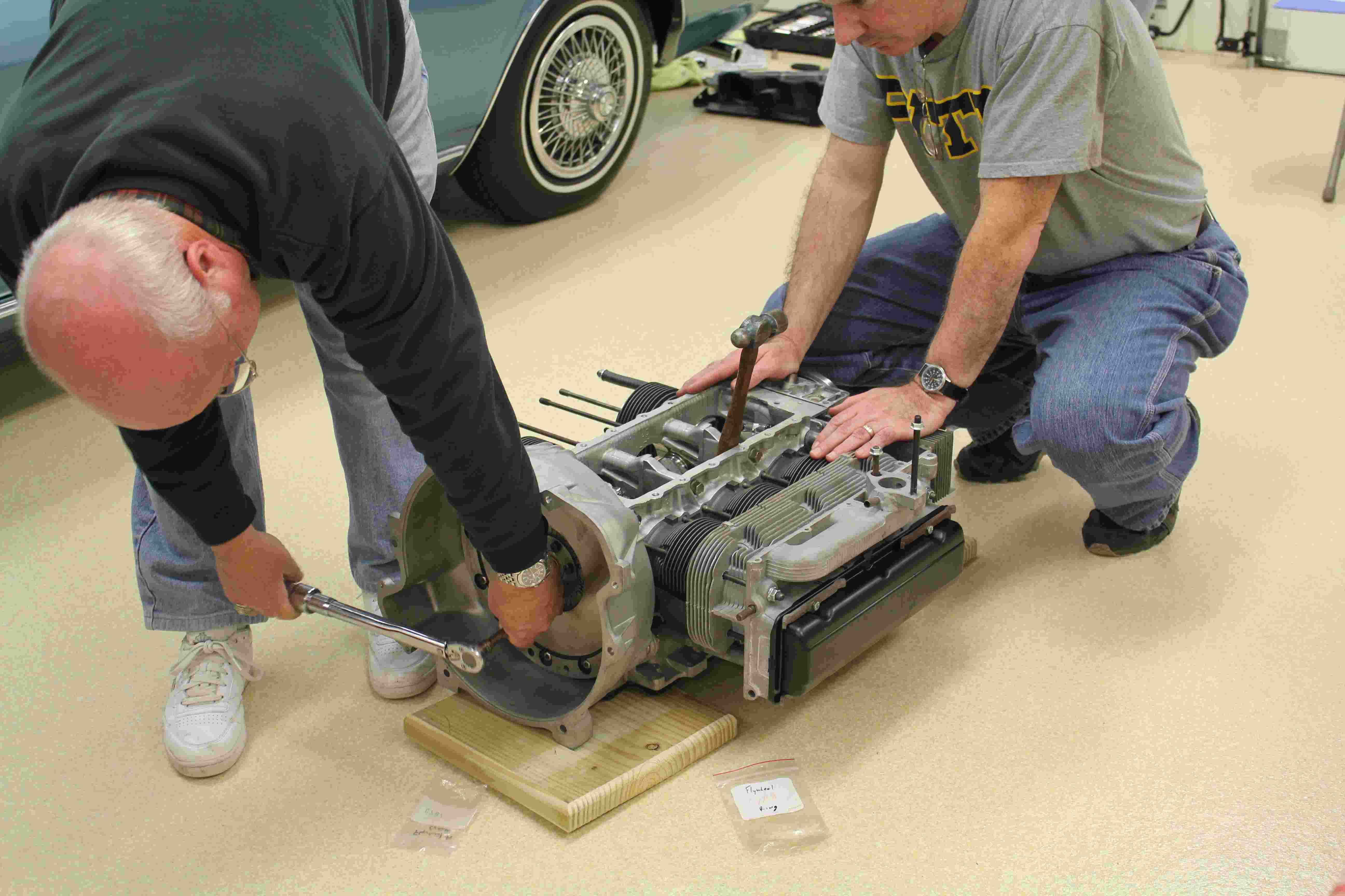
Out comes the torque wrench again!
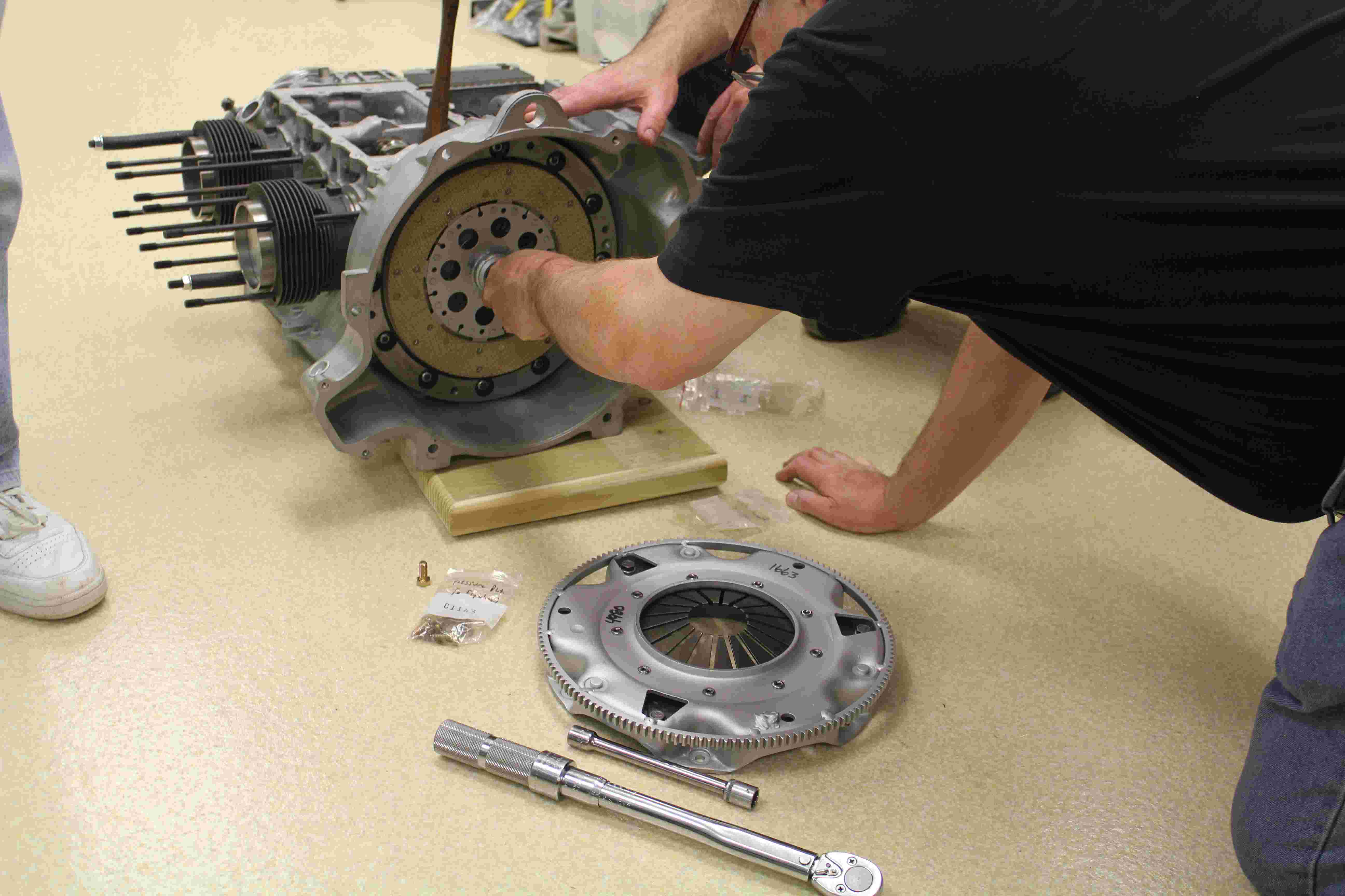
Installing the dummy input shaft.
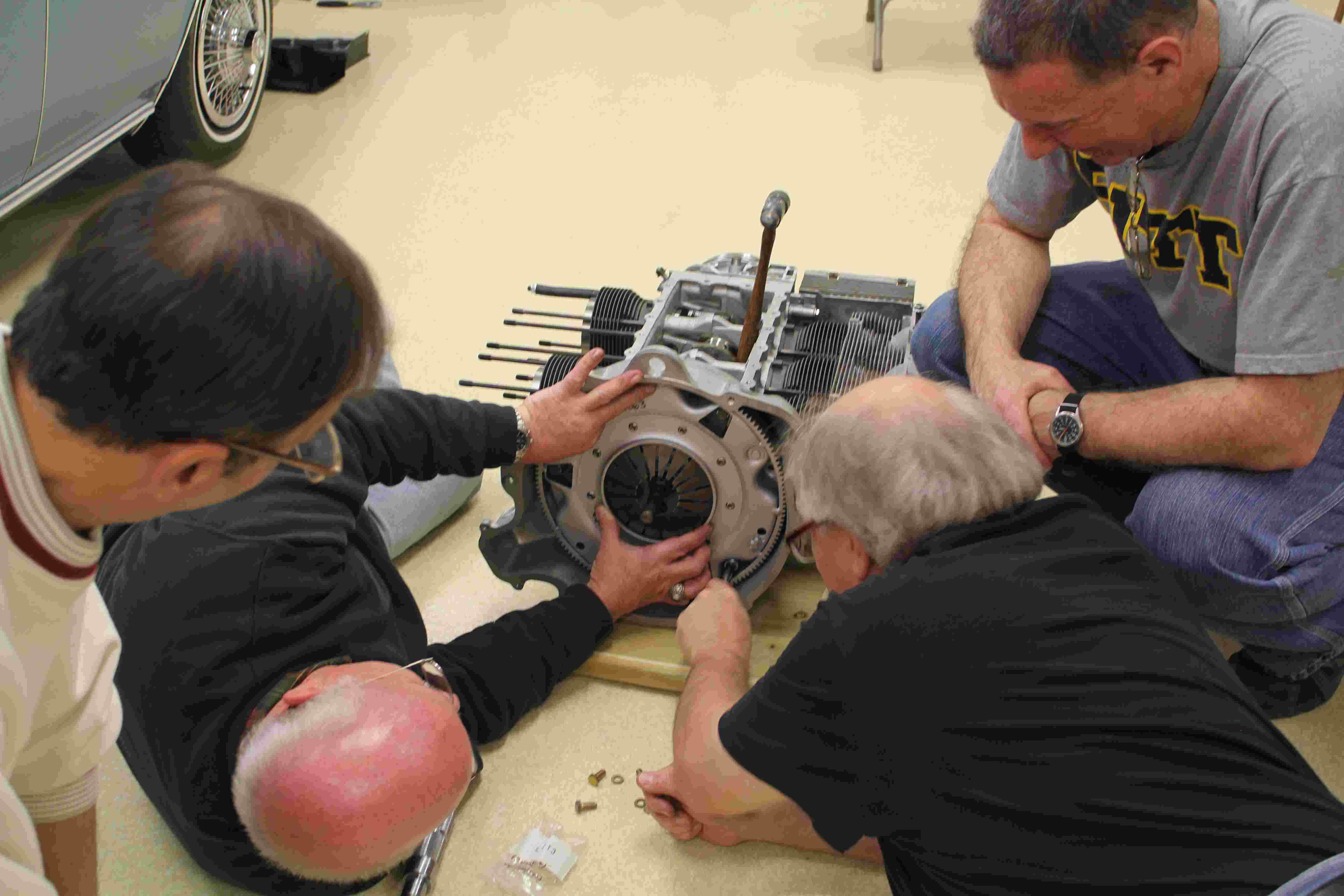
And installing the pressure plate.

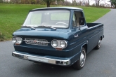
Corvair - The most innovative cars and trucks ever produced in America!
Click HERE to go back to the NJACE Home Page. Edited by redbat01@verizon.net on 10/23/2023